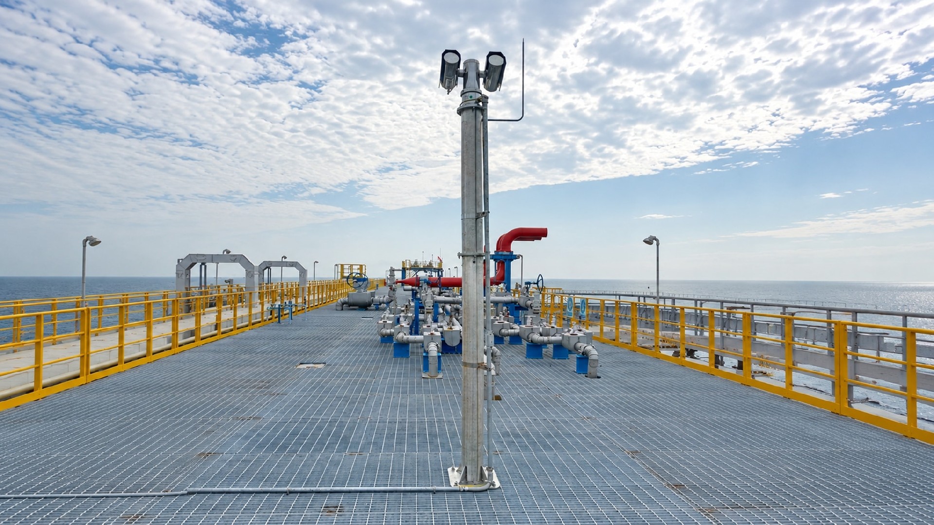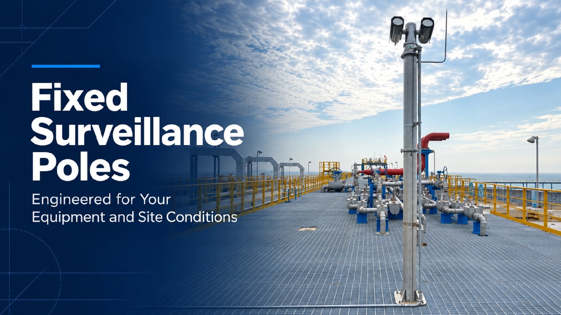
Fixed support structures for cameras, detection instruments, communications equipment and related devices. Pole height, brackets, shaft dimensions and base connections are configured around the equipment layout, site wind conditions and installation requirements.
Available in galvanized steel, stainless steel and aluminum, with drawings, structural calculations and inspection documents provided within the agreed project scope.
Equipment-Specific Interfaces — Brackets configured to equipment drawings and mounting orientations.
Project-Specific Structural Design — Equipment loads, wind area and site conditions considered together.
Coordinated Base Connections — Connections for concrete foundations or verified structural steel platforms.
Technical Documentation — Agreed documents for project review, installation and acceptance.
Poles of the same height may require different shaft dimensions and base connections depending on the equipment, mounting arrangement and site conditions.
| Design Input | Why It Matters |
| Pole height and equipment mounting height | Affect coverage, wind loading and structural response |
| Equipment weight and wind area | Determine loads on the pole and connections |
| Outreach length and mounting positions | Affect bending, torsion and equipment stability |
| Site wind and exposure conditions | Establish the relevant design loads |
| Foundation or platform details | Determine the base connection and supporting structure requirements |
| Corrosion exposure and maintenance access | Guide material and surface treatment selection |
| Equipment operating requirements | Establish any displacement, rotation or vibration criteria |
Send existing drawings for review, or share your equipment details and site photographs for preliminary selection.
Confirm Mounting Positions, Orientation and Connections
Pole-top plates, side brackets, outreach arms and other connections can be configured to your equipment drawings.
Design coordination can cover:
Bolt patterns, fastener sizes and connection dimensions
Equipment mounting heights, orientation and adjustment space
Device spacing and potential obstructions to the field of view
Connector access, cable routing and cable bend requirements
Space for equipment removal and maintenance
Confirming these details before fabrication helps reduce on-site drilling, welding and bracket modifications.
Future equipment can also be considered through agreed mounting provisions and capacity allowances. Later additions should be checked against the original design conditions.
Consider How the Equipment Operates
Pole selection for fixed cameras depends on equipment loading and site conditions. Long-range cameras, PTZ cameras and instruments requiring stable alignment may also need assessment of pole-top displacement, rotation and dynamic response.
Within the agreed scope, we can:
Assess the pole, brackets and base connections against project requirements
Include equipment and accessory weights, wind areas and offset positions
Review operating stability criteria supplied by the equipment manufacturer or project consultant
Provide structural calculations and design documents for project review
Structural capacity and operating stability are assessed separately. Relevant load conditions and acceptance limits are agreed during technical review.
Review the Base and Supporting Structure Together
Flange-mounted poles can be configured for concrete foundations or structural steel platforms, subject to verification of the supporting structure and connection.
| Installation | Key Details to Confirm |
| New concrete foundation | Foundation design conditions, anchor specifications, layout, embedment and installation level |
| Existing concrete foundation | Measured bolt positions, anchor condition and foundation capacity |
| Structural steel platform | Supporting beam locations, connection plates, bolts and local and overall platform capacity |
| Locations near equipment or access routes | Installation clearance, equipment operation, pedestrian access and maintenance space |
For grated platforms, the load path from the pole base to the supporting steelwork must be verified. Grating alone should not be assumed to provide adequate structural support.
Base plate drawings, connection layouts, and interface loads can be provided as agreed for coordination with the project’s civil or structural team.
Galvanized Steel Surveillance Poles
Suitable for a wide range of outdoor and industrial projects. Poles are hot-dip galvanized after fabrication, with additional coatings available according to environmental and project requirements.
Selection priorities: Corrosion protection, equipment loads, fabrication requirements, and maintenance conditions.
Stainless Steel Surveillance Poles
Available in 304 or 316L according to the environment and project specification. Suitable for projects with particular corrosion resistance, metallic appearance or maintenance requirements.
Selection priorities: Salt and pollutant deposits, post-weld treatment, joint details and cleaning requirements.
Aluminum Surveillance Poles
Suitable for projects with specific weight, appearance or material requirements. Alloy grade, shaft dimensions and connections are selected according to loading and site wind conditions.
Selection priorities: Structural stiffness, equipment layout, connection design and protection at dissimilar-metal interfaces.
Cable Routing and Connection Access
Internal cable space, entry and exit points, access doors and external conduit interfaces can be configured around cable quantities, connector sizes and installation requirements.
Cable-entry protection, sealing and drainage should be coordinated with the project’s electrical design.
Grounding and Bonding
Grounding connection points can be incorporated as specified. Lightning protection, grounding and equipotential bonding arrangements should be coordinated with the project’s electrical design and applicable local requirements.
Maintenance Access
Equipment on fixed poles generally requires access from a platform, suitable access equipment or another approved site method. Maintenance space and working conditions should therefore be considered during selection.
Where equipment access is difficult, base-hinged, mid-hinged or equipment-lowering options can be evaluated separately.
| Item | Configuration |
| Structure | Fixed pole |
| Materials | Carbon steel, SS304 / 316L stainless steel or aluminum |
| Pole height | Selected for equipment mounting and project requirements |
| Shaft diameter and wall thickness | Determined by structural design |
| Equipment interfaces | Pole-top plates, side brackets, outreach arms or custom connections |
| Base connection | Designed around foundation or platform conditions |
| Cable and maintenance access | Configured to installation and servicing requirements |
| Surface treatment | Selected according to material and environment |
| Fasteners and accessories | Materials, specifications and quantities confirmed in the order |
| Technical documents | Provided within the agreed project scope |
Supply covers the pole and agreed structural accessories. Cameras, instruments, communications equipment, cables, electrical components and site installation are included only where expressly stated in the quotation.
Manufacturing follows approved drawings and agreed technical requirements. Inspection can cover:
- Materials and supporting certificates
- Pole, flange and equipment-interface dimensions
- Weld appearance and specified additional examinations
- Surface treatment and finish
- Connections, accessories, identification and packaging
Structural calculations, fabrication drawings, interface drawings, material certificates, inspection records and installation instructions can be provided as agreed.
Inspection and Test Plans (ITPs), third-party inspections and witnessed inspections can be arranged where required by the project. Document formats, acceptance criteria and submission dates should be confirmed before order placement.
Fixed surveillance poles can be configured for:
- Oil and gas facilities and tank farms
- Ports, terminals and logistics areas
- Power, water and industrial facilities
- Airports and public infrastructure
- Commercial and campus security installations
For hazardous-area projects, area classification and equipment and electrical installation requirements must also be reviewed. Pole material or installation location alone does not establish explosion-protection certification for the complete installation.
Q1: Can you manufacture interfaces for our equipment brand or model?
A: Yes. Send the mounting drawing, template or model details for review. Bolt patterns, connections, orientation, cable routing and maintenance access are confirmed before fabrication.
Q2: Can one pole support multiple devices?
A: Yes, subject to review of the complete equipment list. Weight, wind area, mounting height and position must be considered together.
Q3: Can the pole be installed on an existing platform?
A: The supporting structure and connection must first be verified. Please provide platform drawings, the proposed base location and site photographs for coordination with the project’s structural team.
Q4: Can you provide documents for review by our local engineer?
A: Drawings, calculations and material and inspection documents can be provided within the agreed scope. Applicable codes, review requirements and document deliverables should be confirmed in advance. Any local endorsement or approval requirements must be agreed separately.
Q5: Can you quote without complete drawings?
A: Yes. We can prepare a preliminary proposal and quotation using the available information, with assumptions and outstanding items identified. Equipment interfaces, structural configuration and drawings are confirmed before production.
Share your project location, pole height, equipment list, mounting arrangement, foundation or platform details, and quantity.
Include any specified wind-loading, material, corrosion-protection or documentation requirements. We can then help define the configuration, scope of supply and required technical documents.