Compare mid-hinged and base-hinged poles for CCTV and lighting projects. Understand lowering paths, clearance requirements, equipment loads and operating systems before specifying a solution.
At sites with restricted vehicle access, frequent servicing needs or difficult access for work at height, hinged poles allow cameras, luminaires and other pole-mounted equipment to be lowered to an accessible maintenance position.
Two common configurations are:
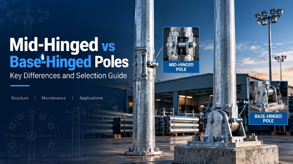
·Mid-hinged poles: The lower section remains fixed while the upper section pivots around a hinge along the shaft.
·Base-hinged poles: The main shaft tilts around a hinge near the base, while the foundation and fixed base section remain in place.
The key difference is which part of the pole moves and the path the equipment follows during lowering. Hinge position also affects clearance, operating forces, cable routing and structural design.
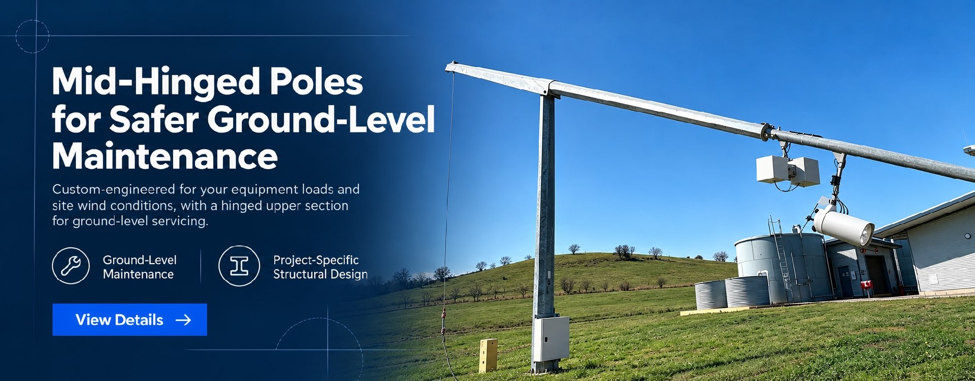
A mid-hinged pole incorporates a pivot within the shaft. During maintenance, the lower section stays upright while the upper section and its equipment rotate down along the designed path.
“Mid-hinged” does not mean the hinge must be exactly halfway up the pole. Its position depends on the upper-section length, equipment arrangement, required maintenance height and operating mechanism.
Depending on the design, movement may be controlled by counterweights, springs or other assistance, or by a dedicated operating device. A mid-hinged configuration does not automatically mean the pole can be operated by one person without tools.
Key points to confirm include:
·The complete travel path of the upper section and equipment
·Any outward swing or downward projection of moving components
·Equipment height, orientation and accessibility when lowered
·Working space around the fixed lower section
·Compatibility of the balancing or assistance system with the actual equipment configuration
A base-hinged pole pivots close to ground level or within the lower base section. The main shaft and mounted equipment tilt in a designated direction, while the foundation and fixed base remain in place.
The term does not simply describe a hinge added to a base plate. Designs may incorporate a dedicated pivot and locking assembly within the lower shaft, and the pivot is not necessarily at ground level.
Depending on the system, lowering may use a matched counterbalance unit, hydraulic device, winch or another dedicated tool. Operating equipment should not be assumed to be interchangeable between different pole systems.
Key points to confirm include:
·The designated lowering direction
·Clearance for the moving shaft and equipment
·Space to fit and operate the lowering device
·Support and access arrangements in the maintenance position
·How correct locking is confirmed after the pole is raised
| Selection factor | Mid-hinged pole | Base-hinged pole |
| Hinge position | Within the shaft, at a design-specific height | Near the base, at a design-specific height |
| Moving section | Upper shaft and attached equipment | Main shaft and attached equipment |
| Fixed section | Foundation and lower shaft | Foundation and fixed base or short lower section |
| Clearance | Travel of the upper section, | Tilting path of the main |
| checks | equipment and any balancing components | shaft and equipment |
| Operating requirements | Depend on load, centre of gravity and assistance mechanism | Depend on the moving shaft, equipment and matched operating device |
| Key procurement information | Hinge height, movement drawing, maintenance position and load limits | Lowering direction, movement drawing, tool configuration and load limits |
Both configurations can be used for surveillance and lighting applications. Neither is inherently stronger, safer to operate or less expensive simply because of its hinge position.
It may be worth assessing first, but the available space still needs to be checked.
Because only the upper section moves, some mid-hinged designs can reduce the clearance needed to lower a long shaft. Actual space requirements depend on hinge height, upper-section length, brackets, equipment, rotation angle and the operating mechanism.
A base-hinged pole generally requires a clear lowering path for a longer moving section. Clearance must include crossarms, cameras, luminaires and other projecting equipment—not just the shaft.
For either configuration, check:
·Walls, trees, buildings and overhead services
·Roads, footpaths and public areas
·Adjacent poles, cabinets and solar arrays
·Space for operators, tools and temporary exclusion zones
·Support and access at the lowered maintenance position
Request a raising and lowering clearance drawing before procurement, rather than relying only on the upright general arrangement.
For example, a pole may lower freely on open ground but become obstructed when installed beside a wall. A clear installation position does not necessarily provide a clear maintenance path.
Hinged poles need to be assessed in both the upright service condition and the raising and lowering condition.
Upright: Wind Loading and Equipment Performance
In addition to equipment weight, provide:
·Equipment dimensions or effective projected area
·Crossarm length and mounting heights
·Equipment orientation and offset
·Site wind design requirements
·Deflection, rotation or other stability requirements for cameras
The hinge, locking assembly and connections form part of the structure and should be included in the design. Camera stability requirements also need consideration alongside structural strength.
During Lowering: Moment About the Hinge
The operating system handles more than the equipment at the top. It must also accommodate the moving shaft, crossarms, brackets and other attached components.
For the same weight, a load further from the pivot generally creates a larger gravitational moment. That moment also changes as the assembly rotates.
The operating device must therefore match the pole configuration, moving mass, centre of gravity and range of movement.
A load rating in kilograms alone is not enough to establish compatibility with every pole height and equipment arrangement.
“Mid-hinged” and “base-hinged” describe the pole configuration. Manual, electric and hydraulic describe aspects of how the system is operated or powered.
There is no fixed rule that:
Mid-hinged poles are always manual, while base-hinged poles are always hydraulic.
Compare operating effort under the specified load, movement control, required tools, staffing and site conditions.
Where portable operating equipment is intended for use across several poles, confirm interface compatibility and rated capacity. Similar appearance does not establish compatibility.
The quotation should state whether operating tools are included. A hinged shaft alone is not a complete, ready-to-operate maintenance system.
| Project condition | Suggested approach |
| Insufficient room to tilt a long shaft | Assess a mid-hinged design and verify its complete movement path |
| A clear, continuous lowering corridor is available | Compare a base-hinged solution and its operating equipment |
| Heavy equipment, long crossarms or large wind areas | Check both service loading and operating moments |
| Several poles will share maintenance tools | Confirm interfaces, capacity and tool availability |
| Camera stability and repeatable positioning are important | Define deflection, connection and post-maintenance checks |
| Neither hinged configuration has sufficient clearance | Consider a fixed shaft with a lowering equipment carriage |
The final choice should reflect project drawings, site layout and the maintenance plan.
When comparing quotations, check whether the scope includes operating equipment, tools, flexible cable arrangements, manuals and training.
Is the hinge on a mid-hinged pole always at mid-height?
No. The hinge height is selected to suit the equipment maintenance position and operating mechanism.
Does the foundation tilt with a base-hinged pole?
No. The foundation remains fixed while the moving shaft pivots near the base. The fixed and moving parts should be identified on the drawing.
Does a mid-hinged pole always need less space?
No. Some designs reduce the clearance needed to tilt a long shaft, but the full travel of the upper section, equipment and assistance mechanism still needs to be checked.
Can both types eliminate the need for access platforms?
They can reduce reliance on access platforms for routine maintenance of equipment that reaches the service position. Installation, fault recovery or work on fixed components may still require other access equipment.
Is a hinged pole automatically passively safe under vehicle impact?
No. A maintenance hinge does not automatically provide passive safety performance. Where required for a road project, the applicable impact requirements and supporting evidence must be confirmed separately.
Can an existing fixed pole be converted by adding a hinge?
Not without a specific assessment. Conversion affects the structure, connections, cables and operating controls and requires an approved design and method.
To compare mid-hinged and base-hinged solutions, provide:
·Pole height, equipment models, weights and dimensions
·Crossarm, bracket and mounting arrangement
·Project location and known wind design requirements
·Site photographs, available maintenance space and obstructions
·Expected maintenance frequency and operating conditions
These details help identify a suitable configuration, movement direction and operating system. If the specification is incomplete, start with the pole arrangement, equipment list and site photographs.
At quotation and technical approval stages, confirm the scope for the pole, operating equipment, tools, installation interfaces and documentation. Final supply should follow the approved design and operating requirements.
Request a Hinged Pole Recommendation